Battery management system
2024
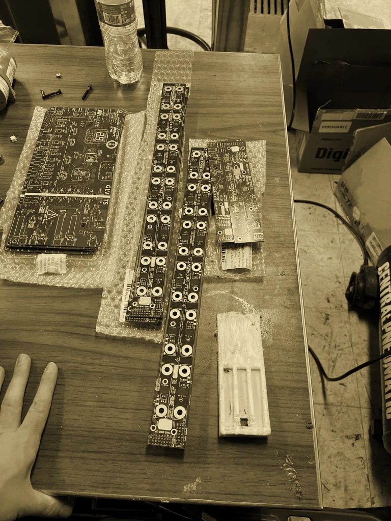
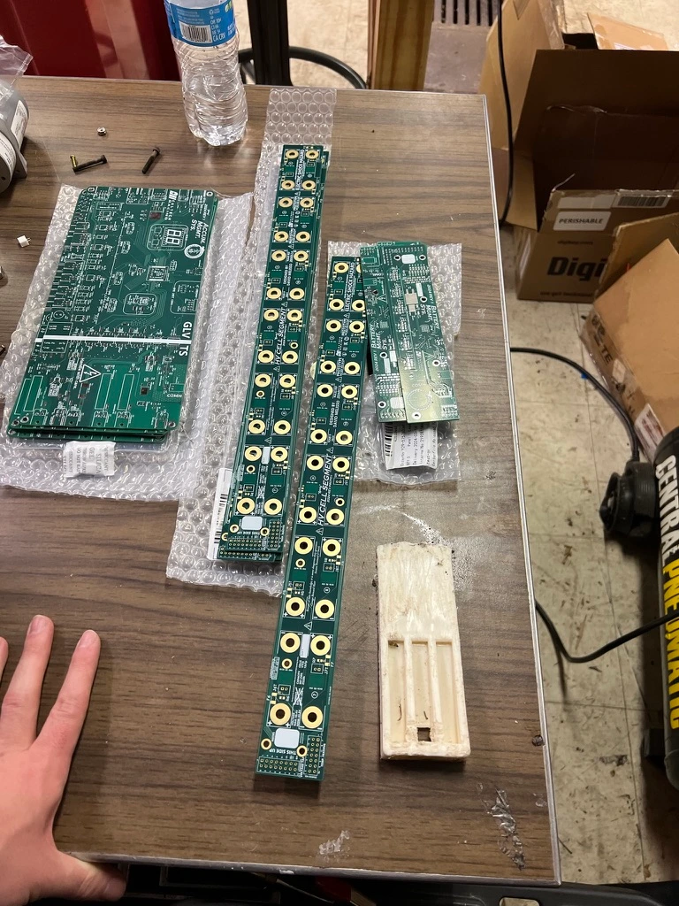
- Pack
- 96s7p, eight segments of 12s7p
- Cells
- Sony VTC6 18650, in Enepaq bolt-terminal modules
- Voltage
- 403.2 V full, 345.6 V nominal
- Energy
- 7.84 kWh
- Monitor
- TI BQ79616, one per segment
- Link
- isoSPI daisy chain
- Busbar
- 2 mm (57 oz) copper, 590 mil trace
- Busbar rating
- 210 A at a 10 °C rise
- Thermistor inputs
- 8 on the IC, for 12 cells
I designed the cell-monitoring hardware for Caltech Racing’s first electric vehicle accumulator. The pack is eight segments of 12s7p, built from Enepaq modules of Sony VTC6 18650 cells: 96s7p in all, 403.2 V at full charge, 345.6 V nominal and 7.84 kWh.
Each segment carries one TI BQ79616, which measures and balances its twelve cells, and the eight are daisy-chained over isoSPI. The segment boards sit inside the enclosure right next to a high-current busbar, which puts out a lot of EMI, so I fenced the isoSPI traces and removed the ground plane underneath them to keep that noise off the link between segments.
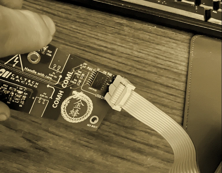
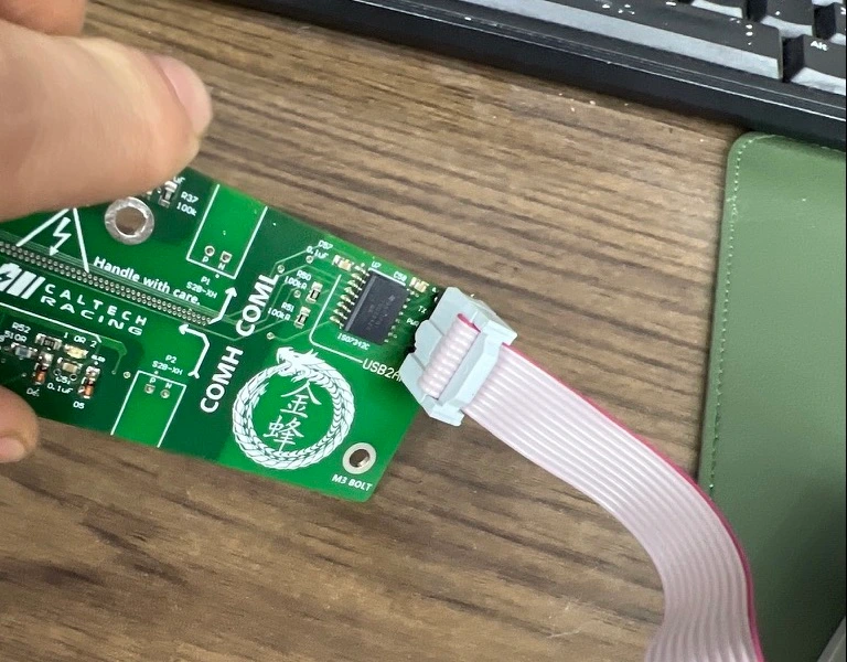
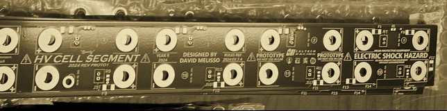
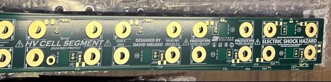
I also designed the busbar board that goes with them: a thick-copper PCB that bolts straight onto the modules’ terminals. It was made in Japan, and it carries current sensing and fusing in the cell interconnect itself, so we didn’t need separate busbar hardware on top of it.
Temperature sensing
The BQ79616 has eight GPIOs for NTC thermistors, but each segment has twelve series cells to monitor. To cover all twelve I paired neighboring cells. A min-voltage circuit takes two cells’ thermistor signals and passes the lower one, the hotter cell, to a single channel, so the IC always reports whichever of the pair is hotter.
The same circuit catches a thermistor that is open or shorted. An out-of-range voltage on either cell pulls the channel low, and the BMS reads that as an over-temperature fault instead of a sensor silently failing open.
Bring-up
A few revisions of the board failed at power-on. The regulator didn’t have the headroom to drive even a status LED, and that kept the rest of the segment from initializing at all. It wasn’t specced for that much load, and the datasheet didn’t make the limit obvious until we hit it in hardware. I traced it by pulling the power stage out and load-testing it on its own before putting it back into the full board.
Since then I check a power stage’s current headroom against the real load, not the datasheet’s typical figures, before committing to a board revision.