Accumulator management system
2024
- MCU
- STM32, bare metal
- Tractive system
- 403.2 V full, 345.6 V nominal
- Low-voltage rail
- 12 V
- Isolated analog
- HCNR201, about 7%
- Current sensor
- DHAB S/125, 80 mV/A
- BSPD delay
- 0.5 s RC, trimmer-adjustable
- HVIL fault latch
- D flip-flop as an SR latch
- Designed in
- Altium
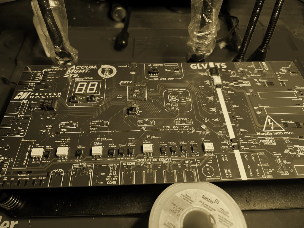
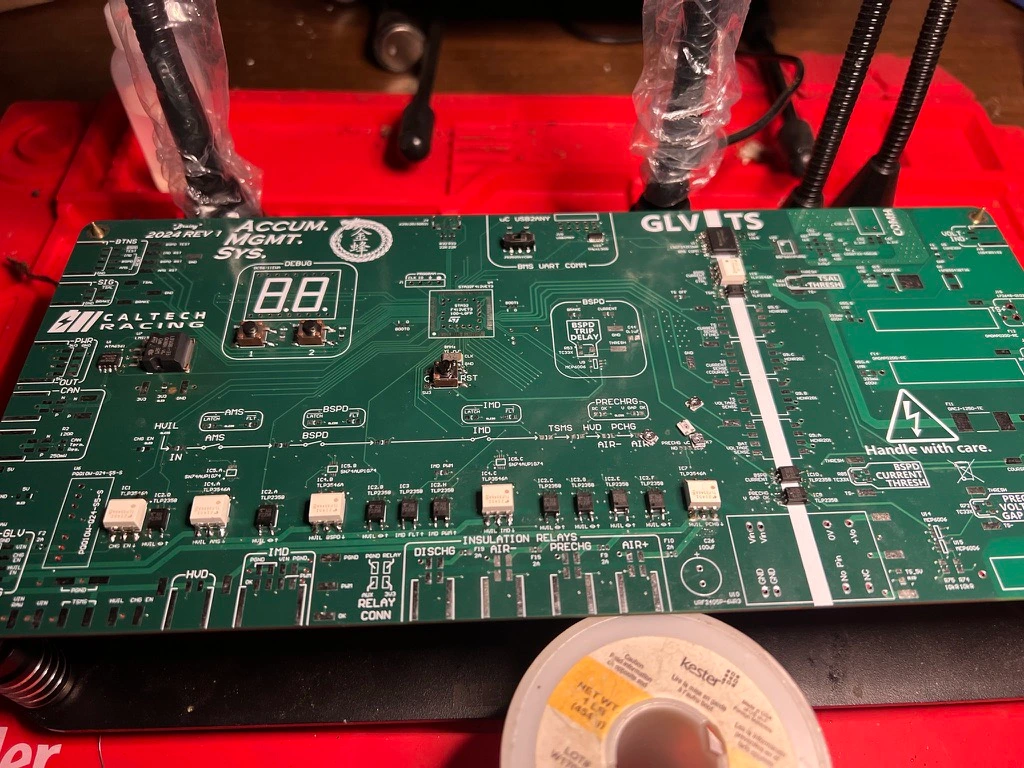
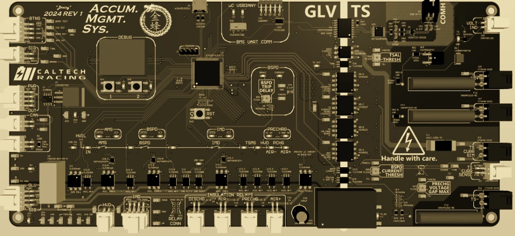
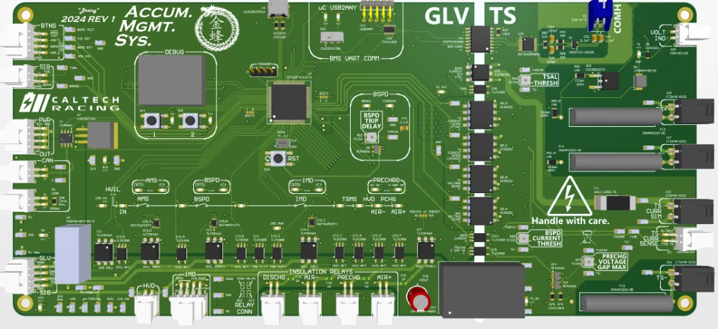
Above the battery management boards in each segment of Caltech Racing’s accumulator sits the safety-critical layer, and I designed that too. It controls the accumulator isolation relays (AIRs), sequences precharge and discharge, and integrates the insulation monitoring device (IMD), fault detection for the brake system plausibility device (BSPD), and the interface to the high-voltage interlock loop (HVIL) in the shutdown circuit.
All of it is on one board, partly to keep integration risk down and partly because the enclosure doesn’t have much spare room. The firmware is bare-metal on an STM32, and it reports heavily over CAN for monitoring and debugging.
Isolated measurement
The AMS needs current and voltage readings from the high-voltage tractive system, both for throttling and for debugging, but they have to cross the barrier to the grounded low-voltage side without weakening the isolation. Digital isolators pass discrete signals cleanly, but they aren’t good at carrying a continuous analog value.
So I used an HCNR201 analog optocoupler. One LED shines on two matched photodiodes. The one on the tractive side drives a feedback loop that keeps the transmitted signal accurate, and the one on the low-voltage side is scaled down to the local logic voltage. That holds the reading to about 7% across the gap.
Precharge
FSAE rules allow either a fixed delay or live voltage monitoring before the AIRs close. I went with live monitoring. It’s more hardware, but it avoids the inrush damage a fixed delay can still allow across a voltage gap.
I also added a lockout the rules don’t require: an RC time-constant monitor that checks the motor controller’s input capacitance is behaving as it should before letting the AIR close. It catches a badly connected motor controller before that turns into an unsafe high-current closure.
Firmware
I wrote the firmware bare-metal, which was fine for one season’s scope, but looking back an RTOS would have made more sense. IMD polling, CAN handling, precharge sequencing and the watchdog all ran as concurrent loops, and that got harder to reason about as the board picked up more jobs. A scheduler would have made that concurrency explicit, instead of something I had to track by hand in the control flow.
Testing
During team testing, which I wasn’t running, the AMS caught out-of-spec voltages in the accumulator. That is exactly what it was there to do.